Undergraduate Embedded Systems Final Assessment · Embedded Systems Developer · 2022.05 · Published: 2022-05-08
Washing Machine Panel based on Embedded Systems using STM32NUCLEO-L476RG
A simulated washing machine control system supporting automatic and manual operating modes
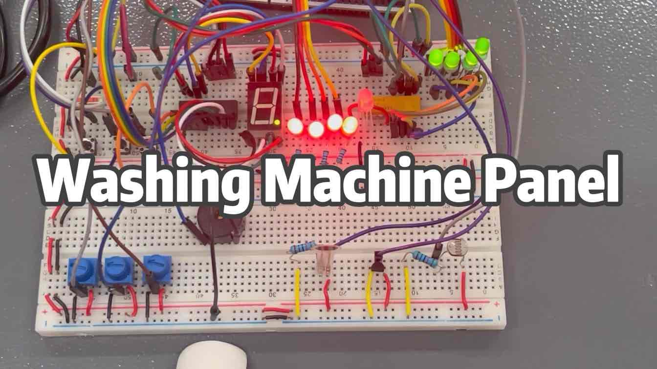
01 · Video
02 · Project Introduction
This project involved the design and implementation of a simulated washing machine control panel using the STM32L476RG Nucleo-64 microcontroller development board.
The system provides two primary control modes:
Fully Automatic Mode
Manual Adjustment Mode
The control panel integrates buttons, LED indicators, a timer display, a pressure sensor, a water temperature sensor, a photoresistor, a thermistor, a potentiometer, and a buzzer. Users can control the power, select an operating mode, execute a washing cycle, monitor sensor parameters, and check the current operating status.
The system also communicates with a computer through a serial interface, allowing operating parameters, button inputs, and washing machine status information to be monitored in real time.
03 · Project Objectives
The project aimed to develop a complete washing machine control system with the following functions:
Switch the washing machine on and off
Select between different washing modes
Indicate the currently selected mode
Measure parameters such as water temperature and pressure
Make operating decisions based on sensor readings
Start and complete the selected washing cycle
Notify the user when the cycle is complete
Display the operating status through a serial interface
Beyond the basic requirements, the project introduced automatic and manual operation, safety checks, abnormal-condition alerts, and cycle pause functionality.
04 · Hardware Components
The washing machine control panel consists of the following components:
STM32L476RG Nucleo-64 development board
Power button
Start button
Confirmation button
Return button
LED status indicators
Timer display
Pressure sensor
Water temperature sensor
Photoresistor
Thermistor
Potentiometer
Buzzer
Serial communication interface
The buttons are used for power control, mode selection, program activation, confirmation, and return operations. The LEDs indicate the current operating stage, while the sensors collect temperature, pressure, and other environmental parameters.
The buzzer provides audible notifications when a washing cycle is complete or when the system detects an abnormal condition.
05 · System Functions
Power Control
The user can switch the simulated washing machine on or off using the power button.
When the system is powered on, it initializes the buttons, LEDs, sensors, buzzer, and serial interface before entering the mode-selection stage. When the power is switched off, the current operation is stopped and the status indicators are disabled.
Washing Mode Selection
The system supports two operating modes: fully automatic mode and manual adjustment mode.
The user can switch between these modes using the control buttons. LED indicators and serial messages are used to confirm the currently selected mode.
Parameter Monitoring
Before and during a washing cycle, the system reads data from the sensors and checks parameters such as water temperature and pressure.
The measured values are used to determine whether the system can operate safely. If an overload, excessive temperature, or another abnormal condition is detected, the washing process is paused and the buzzer alerts the user.
Cycle Execution
After confirming the operating mode and washing program, the user can press the start button to begin the cycle.
The system controls the simulated water inlet, washing, draining, and spinning stages according to the selected mode. LEDs indicate the current stage, and the buzzer notifies the user when the complete cycle has finished.
Serial Status Interface
The system communicates with a computer through a serial connection and displays the operating status using a serial monitor.
The interface can display:
Current power status
Selected operating mode
Current washing stage
Sensor readings
Button inputs
Program running time
Abnormal conditions and warnings
Cycle completion notifications
The serial interface supports both real-time monitoring and software debugging.
06 · Fully Automatic Mode
In fully automatic mode, the system completes the entire washing process according to a predefined sequence.
The primary workflow is:
Power on the washing machine
Initialize the control panel and sensors
Check pressure, temperature, and other input parameters
Select a washing cycle
Execute the water inlet stage
Execute the washing stage
Execute the draining stage
Execute the spinning stage
Complete the cycle and notify the user
The system automatically moves between the different stages without requiring the user to control each operation individually.
During operation, the sensors continuously participate in safety monitoring. If the system detects an overload or excessive temperature, the program pauses immediately and activates the buzzer. The user can also manually pause the washing cycle by pressing the relevant control button.
07 · Manual Adjustment Mode
Manual adjustment mode gives the user greater control over the washing process.
After the system has started and completed its sensor checks, the user can manually select a washing cycle or choose a specific operation to perform independently, including:
Water inlet
Washing
Draining
Spinning
This mode allows the user to adjust the washing process according to their requirements without completing the entire predefined automatic cycle.
Manual mode retains the same safety-monitoring, abnormal-condition alert, and pause functions as automatic mode. If an overload, high temperature, or another unsafe condition is detected, the current operation is paused and the user is notified.
08 · Software Design
The system software was primarily developed in C++ using Mbed Studio or Keil Studio.
The program applies several fundamental programming concepts:
Loops
Conditional statements
Functions
Input and output control
State evaluation
Mode switching
Sensor data processing
Serial output
To improve readability and maintainability, the system was divided into relatively independent functions for power control, mode selection, sensor monitoring, washing-cycle execution, exception handling, and serial communication.
Loops are used to continuously monitor button inputs and sensor states. Conditional statements determine the next system operation according to user inputs and measured parameters.
09 · Input and Output Control
The project integrates the digital input, digital output, and analog input capabilities of the microcontroller.
Input Components
The system reads data from:
Control buttons
Water temperature sensor
Pressure sensor
Photoresistor
Thermistor
Potentiometer
Output Components
The system controls:
LED indicators
Buzzer
Timer display
Serial status messages
Simulated washing-process states
By combining input monitoring with output control, the system can respond to user operations and changing sensor conditions in real time.
10 · Safety and Exception Handling
Several safety-checking and protection mechanisms were added to improve the reliability of the simulated washing machine control system.
These mechanisms include:
Checking sensor parameters before starting a cycle
Continuously monitoring water temperature during operation
Detecting whether pressure or load exceeds the safe range
Automatically pausing the program under abnormal conditions
Activating the buzzer to alert the user
Displaying fault information through LEDs and the serial interface
Allowing the user to pause and resume the program manually
These functions enable the system to make decisions based on external inputs instead of only following a fixed sequence.
11 · Development and Testing
The project was developed using an incremental implementation and integration approach.
Individual components-including the buttons, LEDs, sensors, buzzer, and serial interface-were tested separately. After each component was confirmed to operate correctly, it was integrated into the complete washing machine control program.
The development process included:
Planning the system functions and operating workflow
Building the hardware control panel
Testing individual input and output components
Developing basic control functions
Implementing fully automatic mode
Implementing manual adjustment mode
Adding sensor checks and safety functions
Implementing serial status output
Integrating, testing, and optimizing the complete system
This incremental method made it easier to identify individual module problems before full system integration and provided stable versions of the program throughout development.
12 · Debugging and Optimization
A significant part of the development process involved troubleshooting and debugging.
The main issues included:
Unstable button-input detection
Logical conflicts between control conditions
Incorrect transitions between washing stages
Sensor values affecting program decisions
Loops preventing the system from responding promptly
Inconsistencies between LEDs, buzzer alerts, and serial messages
State-transition problems between automatic and manual modes
To address these issues, I repeatedly inspected and restructured the code. Individual module testing, serial output observation, and conditional-logic adjustments were used to improve the stability of the complete system.
13 · Project Demonstration
The final presentation demonstrated the primary functions of the washing machine control panel, including:
System power control
Automatic and manual mode selection
Washing-cycle selection
Simulation of water inlet, washing, draining, and spinning
Sensor data acquisition
Abnormal-condition detection and buzzer alerts
Manual cycle pausing
LED status indication
Serial status monitoring
Cycle-completion notifications
The demonstration highlighted the interactions between the hardware components and showed how a user could operate the complete washing process through the control panel.
14 · Project Outcome
Through this project, I developed a stronger understanding of the relationship between input, processing, and output in an embedded system. I also improved my ability to develop microcontroller software using C++.
The project provided practical experience in:
STM32 microcontroller development
Digital input and output control
Analog sensor data acquisition
Button and LED control
Buzzer notifications
Serial communication
C++ function design
Loops and conditional statements
Control-flow design
Software debugging and code optimization
The development process demonstrated that embedded-system projects require more than controlling individual hardware modules. Multiple components must operate reliably according to a unified control logic.
Troubleshooting problems related to program logic, state transitions, and component interactions also strengthened my engineering problem-solving and debugging abilities.